
Proton Guiding
/Proton Guiding
Stolterfoht et al. (Helmholtz-Zentrum Berlin) and Ikeda et al. (Atomic Physics Laboratory, RIKEN, Japan) have been investigating the formation of charge patches on insulating capillaries that are 100nm in diameter. Protons can resonately capture a valence electron when they approach a dielectric wall such as SiO2. The proton capture time is around 1 femtosecond and the patch lifetime is around 100 seconds.
This field simulation shows 10ev protons traveling down a silicon dioxide tube lined with 0.2ev charges. The proton beams are bent away from the walls by the charges. These charge spots build up when protons are are captured and stick. The spot grows until new protons are repelled. The spot will dissipate as the protons desorb.

Field simulations of proton bending due to wall charge up
Focus
“Transportation and focusing of accelerated proton beams by means of dielectric channels” K A Vokhmyanina1, L A Zhilyakov2, A V Kostanovsky2, V S Kulikauskas1, V P Petukhov1 and G P Pokhil1
From the paper “Analysis of Adsorption Behavior of Cations onto Quartz Surface by Electrical Double-layer model” Kitamura, Fujiwara (1999) et. Al. it is known that the surface charge of silicon dioxide is governed by the acid-base equilibria of silanol (SiOH) groups . The absorption of cations onto SiO2 can be analyzed using a double layer electrostatic model as Si0- H+.
The paper “Local charge storage and decay mechanism in silica” by Harald Graaf*, Carsten Maedler, Christian von Borczyskowski reported that the activation energy for positive charges on the wall is 0.35eV. They demonstrate charge storage of several electron volts with the half life of the charge in the hundreds of minutes. The accumulation of these charge spots tend to focus the beam away from the walls.

Proton Injection
When protons are introduced into the accelerator from the ion injector there will be a variation in the lateral energy that will be a function of the proton temperature, proton bunching, and asymmetries in the gating electrodes. This lateral energy should be less than 1eV with a forward energy of 5eV. Protons with this little energy will either stick to the wall or tend to be deflected from charged areas on the wall. It is expected that the initial protons in the channel will charge up the walls and that within the 50nm x 50nm channel, the beam will diverge from the walls. This provides both beam cooling and focusing towards the center of the channel.

Exit Dispersion
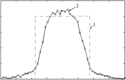
“Guiding of slow neon and molecular hydrogen ions through nanocapillaries in PET” by N. Stolterfoht et. al. 2005 shows transmission profiles for ions passing through 100nm x 10um capillaries. The walls become charged up and effectively guide the ions towards the center of the tube.
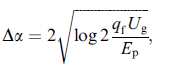
The divergence of the beam was measured as the full width at half maximum (FWHM). where Ep is the projectile energy, qf is the final charge state of the transmitted ions, Ug is the guiding potential near the exit of the capillary. This expression is obtained from the assumption that the angle a _ vs/vp of the transmitted ions relative to the capillary axis is given by the ratio of the vertical and parallel velocities vs and vp (see Fig. 1). Moreover, it is assumed that ions with a perpendicular kinetic energy v2 s =2 larger than qfUg are lost at the surface.The divergence of the beam was measured as the full width at half maximum (FWHM). where Ep is the projectile energy, qf is the final charge state of the transmitted ions, Ug is the guiding potential near the exit of the capillary. This expression is obtained from the assumption that the angle a _ vs/vp of the transmitted ions relative to the capillary axis is given by the ratio of the vertical and parallel velocities vs and vp (see Fig. 1). Moreover, it is assumed that ions with a perpendicular kinetic energy v2 s =2 larger than qfUg are lost at the surface.
This shows that the lining of the capillary prior to exit should be conductive to avoid collecting ions on the wall that cause the exit dispersion. The beam diameter will be controlled by the beam dispersion on exit and the distance between the exit port and the wafer.